
3D Printing Guide
Explore real FDM print paths, compare print settings and understand the choices that shape your part.
How much material belongs inside?
Infill supports the solid faces and contributes to how a part responds to load. More is not always better.
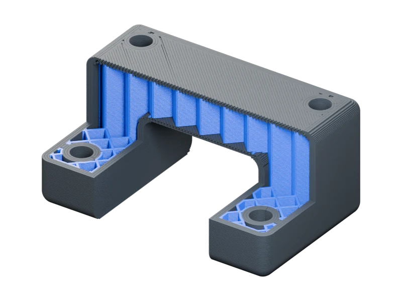
Mounting saddle · 64 × 40 × 30 mm
More support beneath the solid faces.
The Grid cells become smaller. More internal paths support the top layers and occupy the core.
Demonstration PETG profile. Slicer estimates include supports where used; not a quote or a measured strength result.
A useful middle comparison for functional parts. It is an example, not a universal recommended setting.
What to send us
What about strength?
Infill can contribute to stiffness and compression resistance. Geometry, walls and layer bonding still matter.
Design considerations
Explore the printing topics
Inside the print
Infill →
Infill supports the solid faces and contributes to how a part responds to load. More is not always better.
Walls & surfaces →
Perimeters form the shell. Top and bottom layers close the horizontal faces. Explore them separately.
Local reinforcement →
Use sections to review where force passes from a bolt, boss or bearing into the surrounding shell.
Large-part strategies →
Inspect a section through a ribbed equipment tray. Compare dense infill with a more substantial shell, then vary the top and bottom thickness. The mounting towers and recessed deck show why a real part needs more than one global strength setting.
Shape and print direction
Orientation →
Orientation changes the layer direction, support demand and contact surfaces. The fastest setup is not automatically the strongest.
Supports →
Compare the same instrument mount with Snug supports allowed on the model and Organic supports routed from the build plate. Placement is part of the comparison: inspect where each support starts, touches and can be removed.
Design for fewer supports →
This hollow panel adapter has a projecting upper flange. Keep the bore, bolt patterns and top face; change only the 4 mm shoulder beneath the flange. Compare the square underside with a local 45° chamfer.
Bridges & unsupported roofs →
Review the span between supports, the first bridging layer and whether the underside is a functional surface.
Fit and assembly
Fits, holes & clearances →
Start with the function: locating, sliding, rotating or a loose pass-through. Then dimension the two connecting parts, choose a deliberate clearance and verify a coupon in the intended material and orientation. Use these three sections to understand the geometry.
Hole direction & finishing →
A fastener pass-through and a bearing seat need different acceptance criteria. Orientation changes the printed boundary.
Threads & metal inserts →
Inspect three fastening concepts in section: a printed coarse thread, an installed metal insert and a captive nut.
Bolt loads & washers →
Review the load-bearing plastic around metal hardware and the contact area beneath the fastener head.
Finish and appearance
Surface expectations →
Rotate a connector cover to inspect three different surface conditions: the marked top, curved walls, and the supported inner roof. One material is used throughout; lighting and extrusion direction still change the highlights.
Layer height →
Compare the same curved cover at three layer heights. Switch to the closeup to inspect the roof and side walls, then compare the slicer estimates.
Ironing →
Ironing retraces horizontal top faces with a small flow of plastic. Compare the same coupon with and without that extra operation.
Fuzzy skin →
Fuzzy skin displaces exterior perimeter points. It changes the side geometry; it is not a colour or shader effect.
Fine details and CAD
Nozzle size & fine details →
The same plate is sliced at 0.20 mm layer height with three nozzle widths. Inspect the small serial text, sharp star tips, nested squares and narrow strokes. The closeup shows actual paths, including details the slicer omits.
Thin walls & small features →
First inspect how CAD thickness becomes printed paths. Then compare a tall 1.4 mm wall with a sharp root and two internal root fillets. A wall that can be sliced still needs a connection suited to handling and service loads.
Tall walls, ribs & returns →
Keep the 1.4 mm wall thickness and 68 mm height. Compare a free wall with triangular ribs and returned edges. These changes affect printing stability, service stiffness and the available assembly space.
CAD export & small details →
A mesh export approximates CAD curves with flat triangles. Compare a coarse and finer export of the same shape; nozzle size and print settings are separate decisions.
Durability and acceptance
Creep & sustained loads →
Time, temperature and loading duration belong in the design brief. These static shapes illustrate stiffness strategies, not a prediction of creep.
Moisture & material condition →
Material storage and preparation affect printing. We follow the chosen grade’s guidance and check the process before production.
Dimensional acceptance →
Choose a small set of critical dimensions and datums. Treat the remaining geometry according to its function.
One piece or split assembly →
Compare an open housing with two separated sections. The stepped joint illustrates alignment; it is not a validated structural connection.
Surface details
Seam placement →
A perimeter has a start and an end. Compare concentrating those transitions with distributing them. The image shows path starts; it does not simulate pressure-induced blobs.
Top surface patterns →
Top paths affect the visible grain of a broad face. Compare continuous concentric contours with aligned monotonic lines.
Sanding, coating & allowances →
Finishing changes surfaces and can change dimensions. Make the printed geometry compatible with the planned operation.
First-layer interfaces →
The face touching the build plate forms at the start of the print. Its texture and edge shape can affect appearance and assembly.
Bring these decisions to your own part.
Send your CAD and tell us how the part will be used. We can help with the material, fit and print setup.